Home/Capabilities/Photo Chemical Etching

Photo Chemical Etching

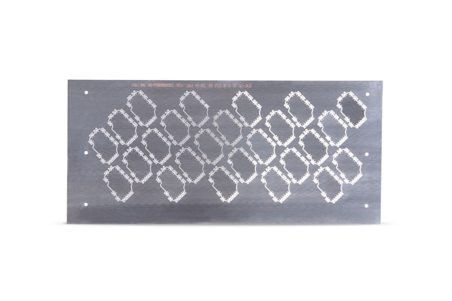
Very precise parts that would be difficult or impossible to make with conventional fabrication — burr-free, stress-free, and without hard tooling.

Photo chemical etching at Mech-Tronics

Process Overview

Photo chemical etching produces highly precise parts that would be difficult or impossible to make with conventional fabrication methods — a technology first used commercially during World War II to produce gun sight reticles. Since then, it has become a vital manufacturing process behind components found in aircraft avionics, medical devices, and electronics.

The guidelines below describe the typical capabilities and limitations of the process, not the absolute limits of what chemical etching can achieve. Contact us to discuss your specific requirements.

The Photo-Chemical Etching Process

  1. Generate artwork on mylar from the Mech-Tronics CAD system or customer-supplied data.
  2. Clean and pre-treat the material.
  3. Apply 1.5 mil dry photo-resist mylar film to the metal sheet to be etched.
  4. Expose the film via UV light to transfer the piece part photographically to the treated sheet.
  5. Develop the image on the metal sheet to fix it in place.
  6. Chemically remove the unprotected areas by etching with the proper acid within an enclosed chamber.
  7. Rinse and strip the photo-resist film from the sheet.
  8. Proceed to next operations — forming, dip brazing, hardware insertion, silk screening, finishing, etc.
Why It Wins

Advantages of Chemical Etching

Superior for Prototypes

Excellent precision, repeatability, and accuracy with quick turnaround. Engineering changes and modifications are made quickly, easily, and inexpensively.

Low Cost

The chem-etch photo tool is far less expensive than hard tooling — and unlike hard tooling, part complexity is not a cost driver.

No Hard Tooling

No major investment, no die maintenance or repair. Photo-tool lead time is normally 1–2 weeks and can be shortened if necessary.

No Metal Stress or Deformation

Chem-etched parts remain flat because metal removal is chemical, not mechanical.

Burr Free

Secondary deburring is eliminated since there is no metal-to-metal contact stress.

Material Properties Unchanged

Temper of the metal is not changed and magnetic properties are not affected.

Tolerances & Materials

  • Some bevel undercutting occurs at the edges of all dimensions — approximately 20% of material thickness when etching the sheet from two sides.
  • Hole size generally cannot be less than material thickness.
  • Outside radius corners are sharper than inside corners.
  • Inside radius corners are usually limited to one half the material thickness.

Materials Commonly Used

Aluminum, Beryllium Copper, Brass, Copper alloys, Nickel Silver, Phosphorous Bronze, Stainless Steel, and Steel — in material thicknesses usually within a range of .0005" to .060".

Hole Sizes

Material ThicknessMinimum Hole DiameterTolerance ±
.001"–.005"Material thickness.001
.006"–.010"Min. 110% of material thickness.0015
.010" and thickerMin. 125% of material thickness.002

Minimum Material Between Parts or Etched Areas

Material ThicknessSize of Material Web
Less than .005"Minimum of thickness of material
Over .005"125% thickness of material
Request a Quote